Installers should only enable channels with connected accessories and then label, icon, and configure each input or output.
Digital inputs can be set to trigger on high, low, or open-circuit signals, while outputs can be set to Always On, Input Control, or User Control. Inverter channels can be enabled for REDARC inverters with options for monitoring and control.
Voltage and temperature inputs can be configured with labels and alarms, and water tank sensors must use inductive probes. All settings are managed through the RedVision Pro Display or App.
REDARC recommends seeking the support of a qualified auto electrician or technician.
Important
For your safety, REDARC recommends installation by a qualified technician. Seek support from a REDARC recommended dealer or installer - Find Your Local Installer
If your system contains a TVMS Prime please follow the configuration guide below.
This information is applicable to the following products:
- TVMS Prime (TVMS1280)
If your system contains a TVMS Prime (TVMS1280) please follow the configuration as below:
If an Output Channel doesn’t have any installed accessories, leave the Output disabled.
Please note: If you are adding a TVMS Prime to an already configured system, you will need to Read Device and connect to your system before completing the instructions below.
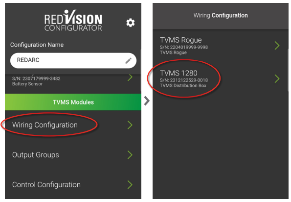
Under the TVMS Modules heading, tap Wiring Configuration.
Tap TVMS 1280.
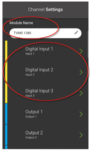
Under Module Name, if multiple TVMS Modules (Rogue or Prime) are installed, rename each TVMS Module for easier identification.
The yellow bars represent digital inputs, these control a channel by turning it on or off when either an input voltage or open circuit is detected by the digital input channel.
For example: The digital input can be used to turn auxiliary rear lights on when the vehicle is put into reverse.
Tap one of the Digital Inputs that has installed accessories.
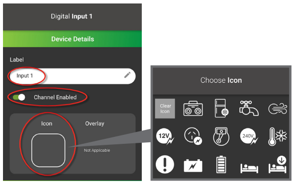
Add a Label.
Ensure Channel Enabled is enabled.
Set an Icon.
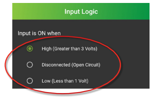
Next, under the Input Logic heading, set Input is ON when.
Below defines the options:
High (Greater than 3 Volts): When the digital input receives an input voltage above 3 volts, the digital input turns on.
Disconnected (Open Circuit): When the digital input has a voltage input and the input is taken away, the digital input turns on.
Low (Less than 1 Volt): When the digital input receives a ground input and the input voltage drops below 1 volt, the digital input turns on.
Tap Save.
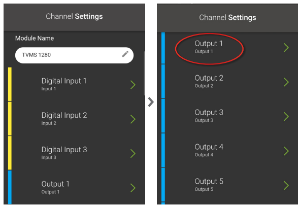
The blue bars represent the Output Channels.
Output 1-5 (F0-F4 on the distribution box) are 10A channels and Output 6-10 (F5-F9 on the distribution box) are 30A channels.
Tap one of the Output Channels (1-10) that has installed accessories.
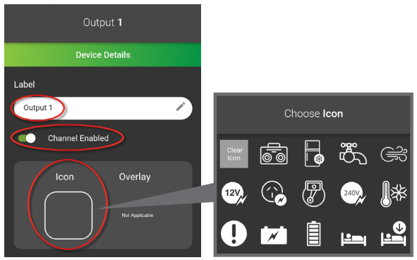
Add a Label.
Ensure Channel Enabled is enabled.
Set an Icon.
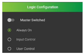
Next, under Logic Configuration set the Master Switch to on or off.
On will allow the channel to turn on or off when Master Switch is enabled on the RedVision Pro Display or RedVision App.
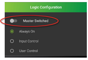
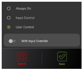
Set the channel to Always On, Input Control or User Control.
If Always On is selected;
Always On will lock the output for constant power to the accessory.
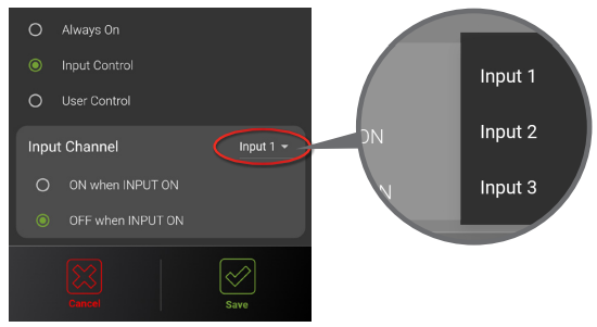
If Input Control is selected;
Set the Input Channel.
Set the Input Channel to ON when INPUT ON or OFF when INPUT ON.
This will enable the output to switch on or off depending on the digital inputs.
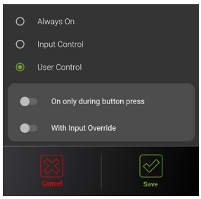
If User Control is selected;
User Control will enable on/off operation when using the soft keys on the RedVision Pro Display or RedVision App.
Additionally this can be configured as a Momentary Switch (On only during button press) or With Input Override from a digital input.
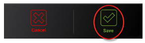
Tap Save
If you have an Inverter connected to the TVMS Prime, follow the instructions below:
If you do not have an Inverter connected, leave the Inverter Channel disabled.
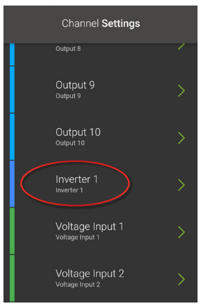
The dark blue bar represents the Inverter Channel.
This communication line is only compatible with REDARC inverters.
Tap Inverter 1.
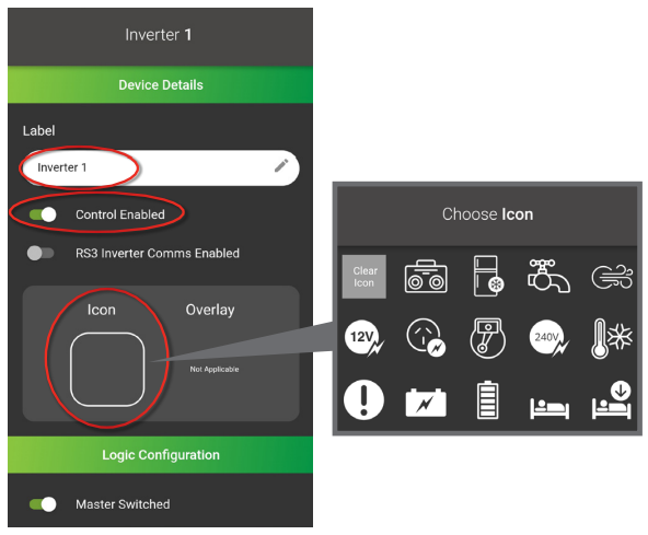
Add a Label.
Ensure Control Enabled is enabled.
If you have an RS3 Inverter and TVMS Prime with a serial number greater than 2310119116-0001, you can turn on RS3 Inverter Comms Enabled to monitor the output voltage and output power of your inverter on the RedVision Pro Display and RedVision App.
Set an Icon.
Under Logic Configuration set the Master Switched to on or off.
On will allow the Inverter to turn on or off when double tapping the Master Switch on the RedVision Pro Display and RedVision App.
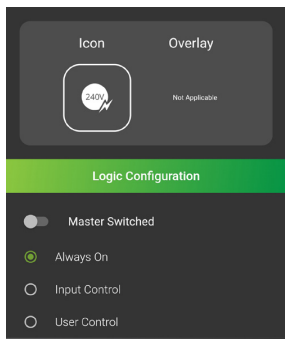
Set the Inverter to Always On, Input Control or User Control.
If Always On is selected;
Always On will lock the output for constant power to the Inverter Channel.
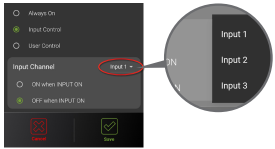
If Input Control is selected;
Set the Input Channel.
Set the Input Channel to ON when INPUT ON or OFF when INPUT ON.
This will enable the output to switch on or off depending on the digital inputs.
If User Control is selected;
User Control will enable on/off operation when using the soft keys on the RedVision Pro Display or RedVision App.
Additionally this can be configured as a Momentary Switch (On only during button press) or With Input Override from the digital input.
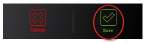
Tap Save.
To configure the Voltage Inputs, follow the instructions below:
Optional: if you choose not to display voltage information, leave the channel disabled.
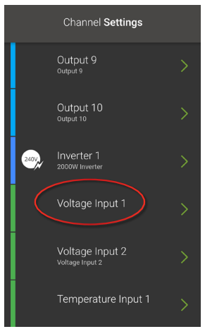
The green bars represent Voltage and Temperature Inputs.
Voltage Input 1 is measured using the positive and negative of the Digital Input connector. Voltage Input 2 is measured from the TVMS Prime input power supply.
Tap one of the Voltage Inputs, to configure.
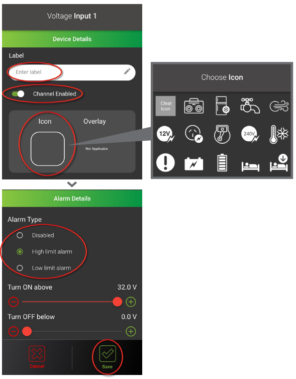
Add a Label.
Ensure Channel Enabled is enabled.
Set an Icon.
Set Alarm Type, if necessary.
The alarm will appear as a warning on the RedVision Pro Display once the specified voltage limit is reached.
Tap Save.
Repeat this process for the remaining Voltage Input.
If you have a Temperature Probe(s) connected to the TVMS Prime, follow the instructions below:
If a channel has no Temperature Probe(s) connected, leave the channel disabled.
Temperatures are measured from the probes supplied with the TVMS Prime.
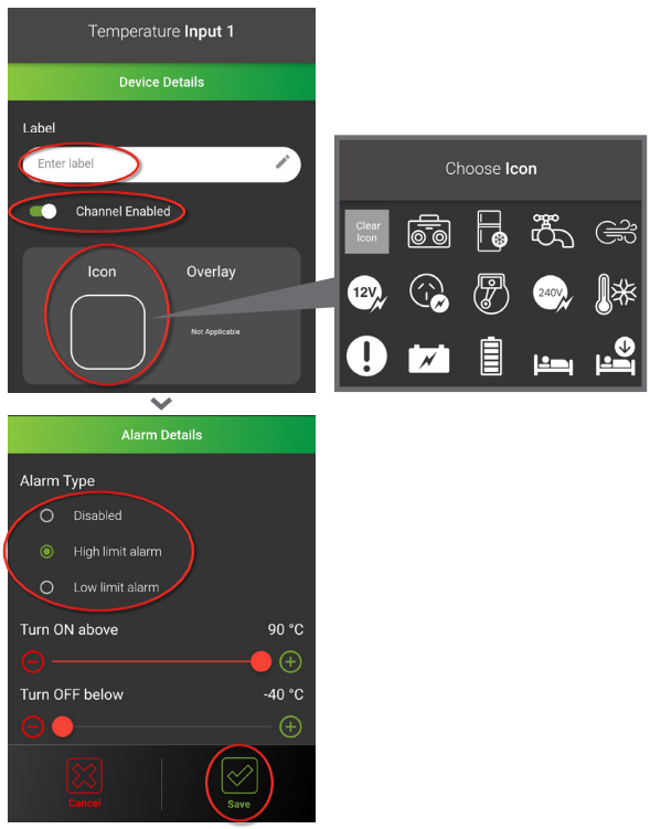
Tap one of the Temperature Inputs that has a probe connected.

Add a Label.
Ensure Channel Enabled is enabled.
Set an Icon.
Set Alarm Type, if necessary.
The alarm will appear as a warning on the RedVision Pro Display once the specified temperature limit is reached.
Tap Save.
Repeat this process for the remaining Temperature Input that has a probe installed.
If you have Water Tank Probe(s) / Sensor(s) connected to the TVMS Prime, follow the instructions below:
If a channel has no Water Tank Probe(s) / Sensor(s) connected, leave the channel disabled.
The orange bars are the Water Tank Level Sensors.
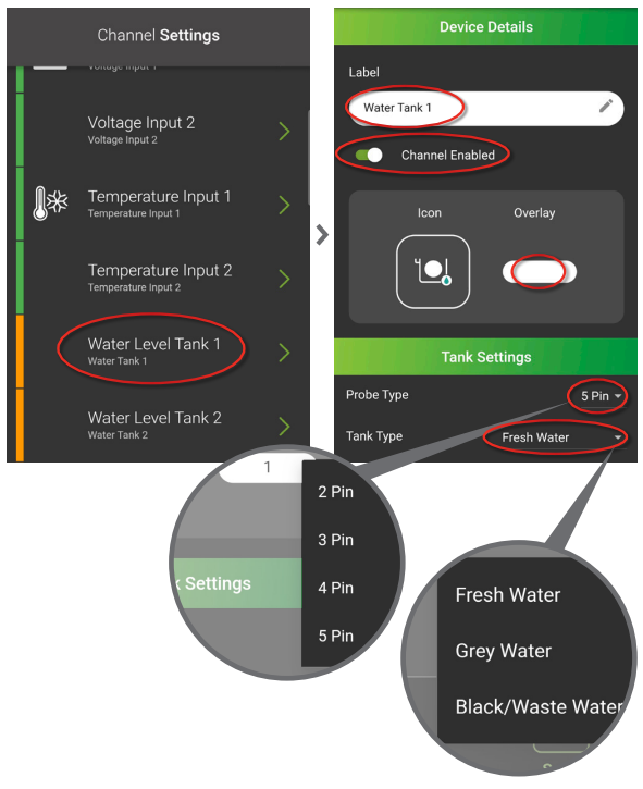
Tap one of the Water Level Tanks that has a probe or sensor installed.
Add a Label.
Ensure Channel Enabled is enabled.
The icon will automatically be set, you cannot edit the icon for Water Level Tank channels.
Optional: Set Widget Overlay (eg: 1 for Tank 1 or G for Grey Water).
Under Tank Settings, set Probe Type.
The water probes / sensors installed must be inductive type sensors, as resistor type sensors are not compatible with TVMS Prime (if you are unsure of your probe type, refer to
manufacturer specifications).
Set Tank Type.
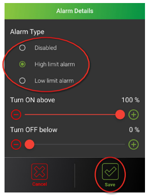
Set Alarm Type, if necessary.
The alarm will appear as a warning on the RedVision Pro Display once the specified Water Level Tank percentage limit is reached.
Tap Save.
Tap Back until you are back at the main screen.
Repeat this process for the remaining Water Level Tanks that have a probe or sensor installed.
To view or download the full RedVision Configuration guide, click here.