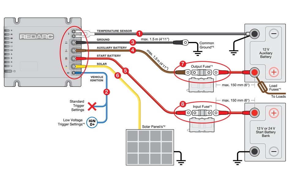
If the BCDC Alpha shows a flashing H status LED with the Control Button LED on, it indicates a hard fault caused by wiring or installation issues, and charging will stop. Common causes include reverse polarity on the auxiliary battery or loose/poor connections at the start battery, fuse holder, or ground.
To resolve, check and correct wiring, clean and secure all connections, verify solid crimps, then perform a full power cycle reset by disconnecting and reconnecting components in the correct order.
REDARC recommends seeking the support of a qualified auto electrician or technician.
Important
For your safety, REDARC recommends installation by a qualified technician. Seek support from a REDARC recommended dealer or installer - Find Your Local Installer
This information is applicable to the following BCDC Alpha chargers:
- BCDC Alpha 25A (BCDC12025B)
- BCDC Alpha 50A (BCDC12050B)
What does this look like?
The BCDC Alpha H status LED and Control Button LED will flash.
This fault condition is a hard fault and therefore the Control Button LED will be on while the H status LED flashes.
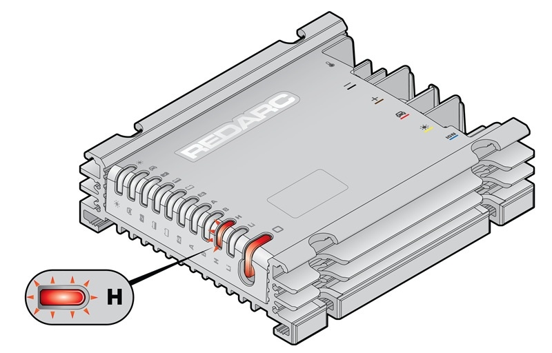
What does the flashing 'H' LED mean?
This fault indicates that the BCDC Alpha has detected an issue with the wiring and/or installation.
Will the BCDC Alpha still charge my battery in this condition?
In this fault condition, being a hard fault, the BCDC Alpha will cease charging.
What can cause this fault?
- Reverse Polarity power supply
- Loose or poor ground to the BCDC Alpha
How to determine the cause?
Below is a list of the common causes and repairs.
A) REVERSE POLARITY
Upon initial installation, if the auxiliary battery terminals (+ and -) are wired to the BCDC Alpha in reverse polarity. Things to check:
- Ensure wiring to BCDC Alpha is correct.
- If wiring is incorrect, rectify wiring.
- Refer to step B.
B) LOOSE CONNECTION AT THE START BATTERY TERMINAL/FUSE HOLDER OR LOOSE GROUND CONNECTION AT THE BCDC
Things to check:
- Ensure connection points are clean, not damaged or loose.
- Remove the battery terminal and ensure a clean surface area is provided for the terminal.
- Inspect the ground wire (-) to ensure it has a suitable ground connection, including ensuring the terminal is attached to bare metal (an unpainted surface).
- Ensure each crimp connection is strong, a small tug on each wire can confirm this.
- Refer to step C.
C) CARRY OUT POWER CYCLE PROCEDURE
Once steps A and B have been completed, it's advisable to carry out a full power cycle to reset the BCDC Alpha.
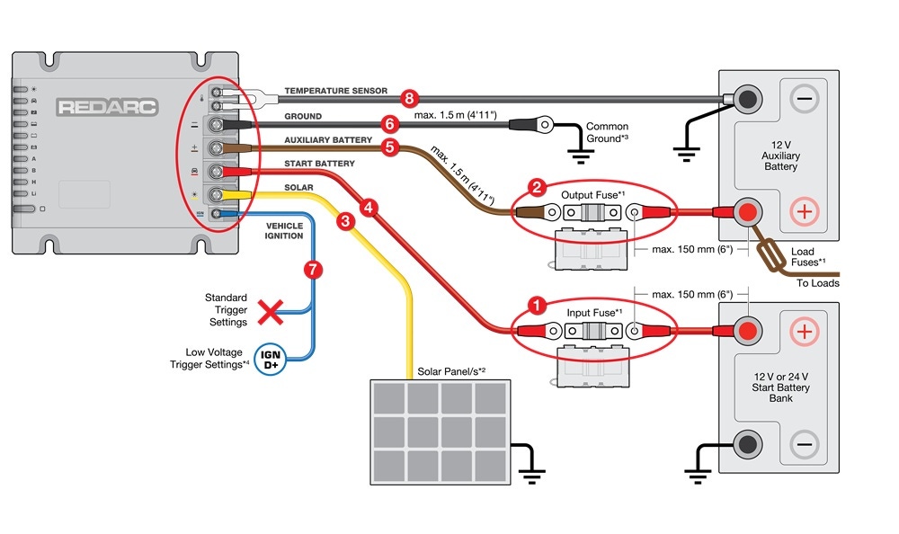
This is achieved by following the disconnection and reconnection procedure listed below:
DISCONNECT PROCEDURE
- Start Battery Fuse
- Auxiliary Battery Fuse
- Solar
- Start Battery
- Auxiliary Battery
- Ground
- Vehicle Ignition
- Battery Temperature Sensor
RECONNECT PROCEDURE
After being disconnected for 5 minutes, reconnect the BCDC in the following order:
- Battery Temperature Sensor
- Vehicle Ignition
- Ground
- Auxiliary battery
- Start battery
- Solar
- Auxiliary Battery Fuse
- Start Battery Fuse
- Re-check operation
If problem persists, contact REDARC Technical Support.